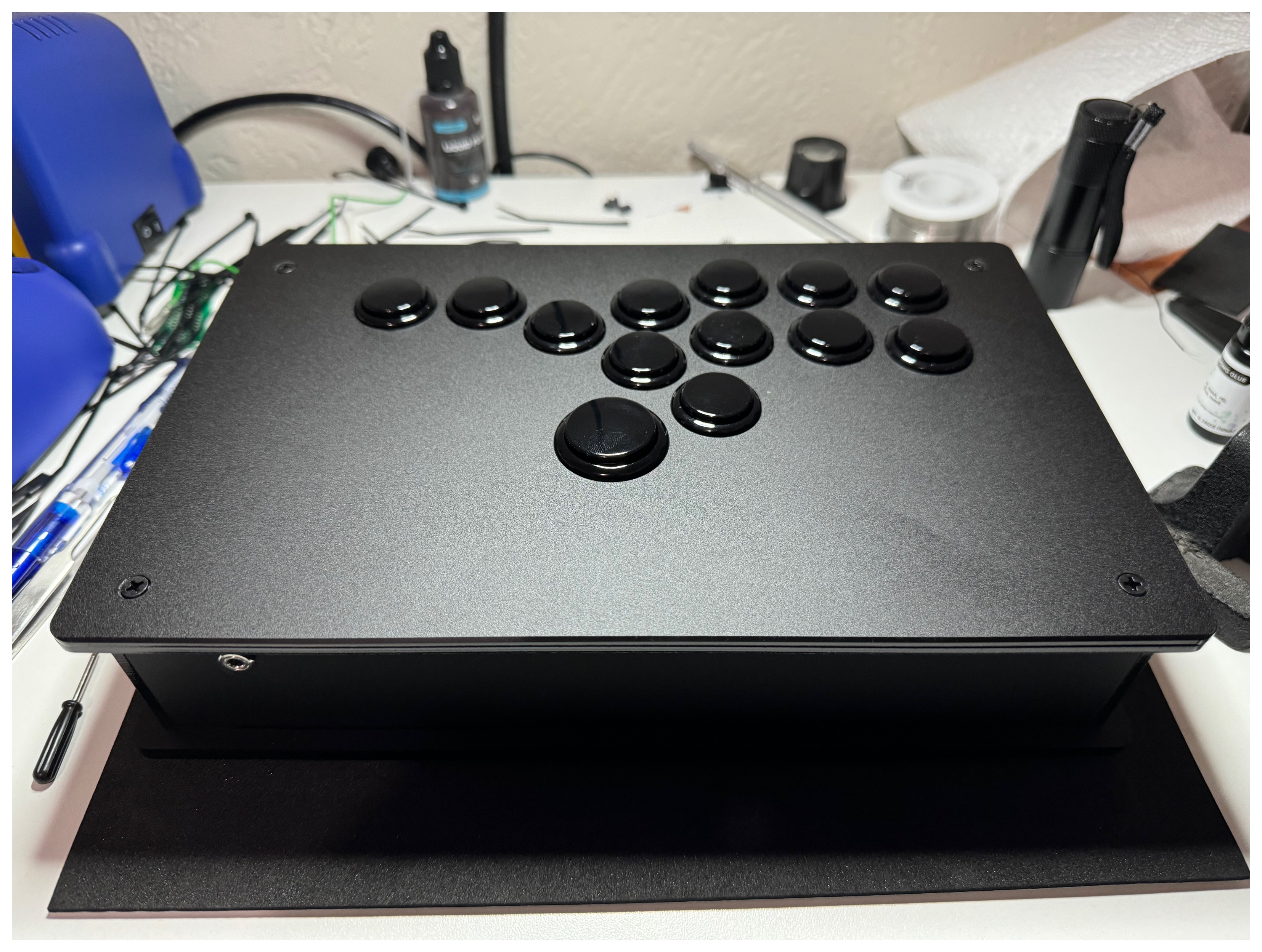
A leverless (or stickless) controller is a type of arcade controller that uses buttons for movement controls instead of an arcade stick. One popular example is the Hit Box. I recently created a custom leverless controller using the electronics from Playstation 5’s DualSense controller, an enclosure purchased from Eternal Rival, and various other components. The practice of utilizing an existing game controller’s electronics in a custom arcade controller is commonly referred to as “padhacking”. Here, I document the parts I used and steps I took to complete this project.
Goals
The practice of building custom arcade controllers (leverless or otherwise) is quite common and there are a wide variety of controller boards available that are paired with pseudo-standard wiring harnesses for connecting to the buttons. I instead opted to use the DualSense electronics in order to gain the option for wireless functionality when I desire it and for excellent compatibility with many hosts (PS5, computers, iOS devices, etc.). For this project, I had a few goals in mind:
-
Goal 1: The implementation should be modular. No two boards should be connected together via soldered wires.
-
Goal 2: Reworks to the DualSense MLB should be as minimal as possible.
-
Goal 3: All of the existing DualSense controller functionality should be preserved except for LED indicators, the touchpad surface, the microphones & speaker, the rumble motors, and the adaptive triggers. All physical buttons should be made available on the controller. Both the USB-C and audio ports should be made available.
Design
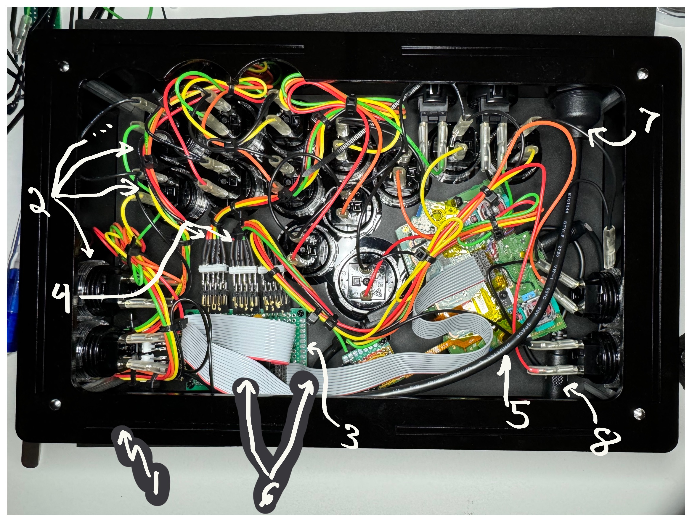
There are 8 fundamental components in this project:
-
The enclosure
-
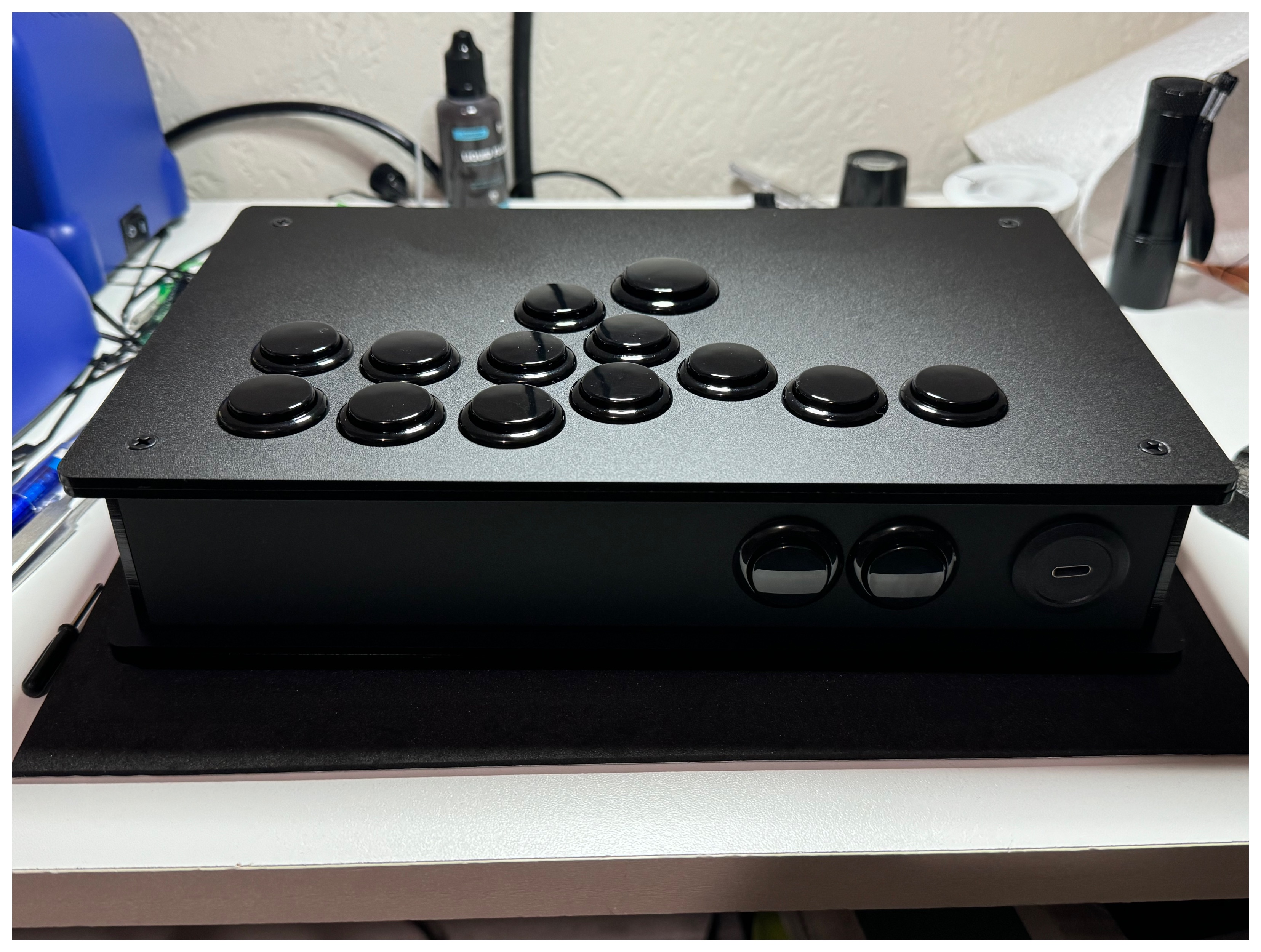
The 19 arcade buttons (12 24mm buttons and 1 30mm button on the top, and 2 24mm buttons each on the north, east, and west sides)
-
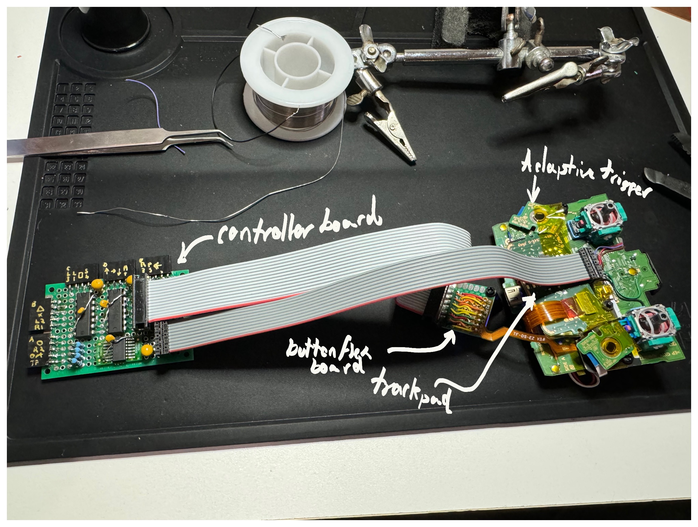
The controller board: a protoboard that receives all of the button signals and maps them to the DualSense’s inputs (performing some signal modification as necessary, discussed below)
-
The 5 wiring harnesses which connect the buttons to the controller board
-
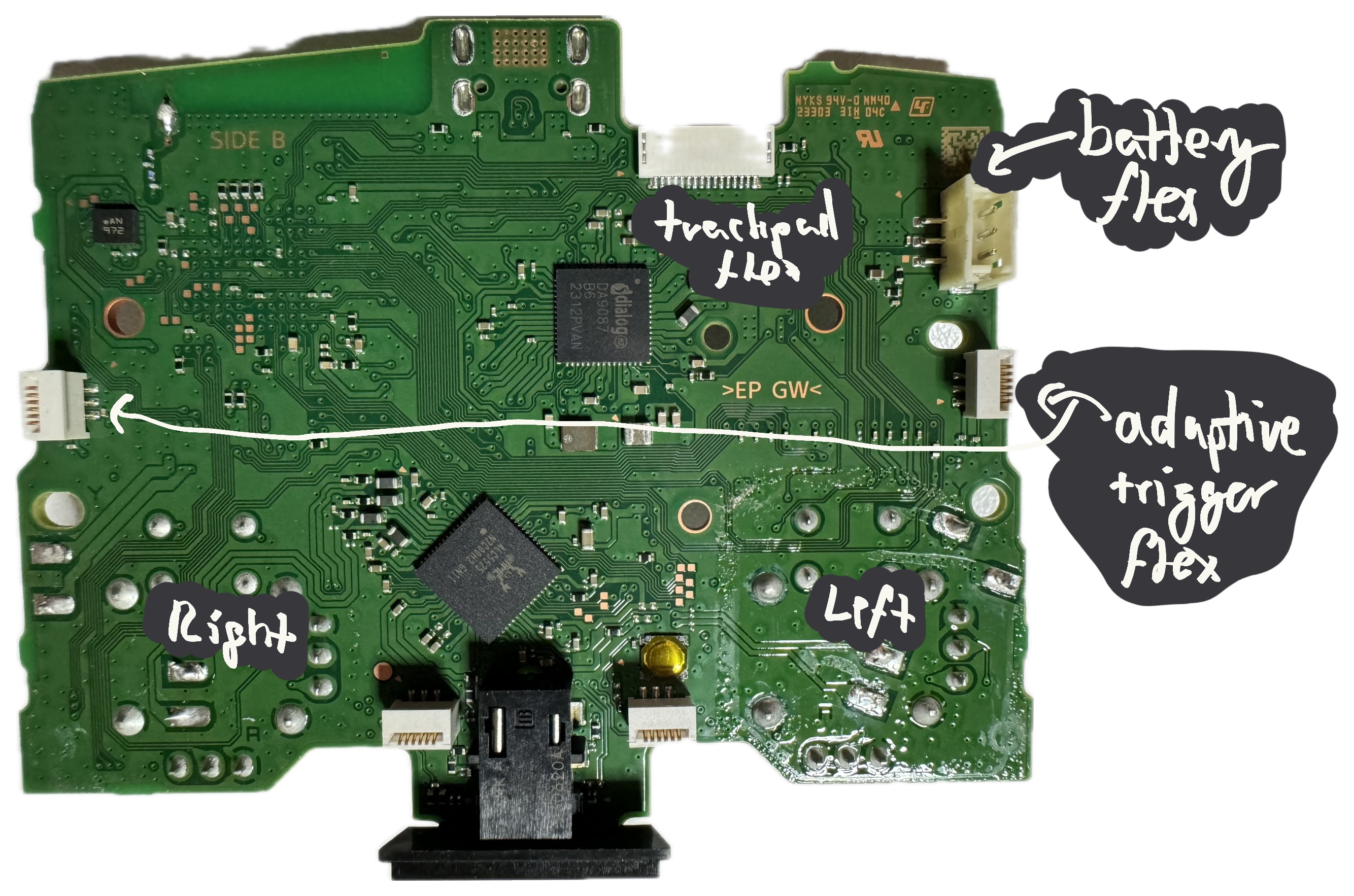
The reworked DualSense MLB and its satellite parts (adaptive trigger boards, touchpad board, button flex breakout flex+board, and battery)
-
The 2 ribbon cables which connect the controller board to the DualSense MLB
-
The USB-C passthrough cable
-
The audio jack passthrough cable
Bill of Materials
As this was the first time I’ve built a device like this, I ordered more than I needed. However, for this list, I’ve tried to include only the things that are necessary (with a couple of hacks that could be cleaned up as noted by asterisks and discussed in the following sections). In some cases, I may have had parts already, so I linked the closest thing that I think should work.
-
Enclosure: Eternal Rival’s Mid-Tier Stickless Mini
-
Buttons
-
12× 24mm buttons for the top — after some research, I decided to use Samducksa Crown SDB-202
-
1× 30mm button
-
6× 24mm snap-in buttons for the sides (sidewalls of this enclosure are incompatible with screw-in buttons)
-
-
Electronics Parts
-
Electronics Components
- 8× 10K resistors
- 3× 10µF capacitors
- 3× 0.1µF capacitors
- 2× CD74AC00E Quad-NAND ICs
- 1× SN74LVC07ANSR Hex Open-Drain output buffer
- 1× SOIC-14 to DIP-14 adapter
- 2× 14-position, 2-row, 0.1" pin header
- 1× 10-position, 2-row, 0.1" pin header (through-hole)
- 1× 10-position, 2-row, 0.1" pin header (surface-mount)
- 5× 5-position, 1-row, 0.1", right-angle receptacle headers*
- 5× 10-position, 2-row, 0.1", right-angle pin header*
-
Mechanical Components & Adhesives
-
Tools
- Soldering iron with angled tip
- Right angle tweezers
- Scalpel
- Flush cutters
- High-quality wire strippers
- Temperature-resistant workspace pad
- Helping hands
- Magnifying glasses
- Magnifying loupe
- Fine solder wire
- Solder wick
- Solder flux (liquid worked well)
- Drill with 5/64" and 7/64" drillbits (or 2mm and 2.5mm drillbits if you have access to metric drillbits), as well as a 1/4" drillbit
- Dremel with cutting blade (for cutting PCBs)
DualSense MLB Rework
I purchased a new DualSense controller (as opposed to a used one) for two reasons:
-
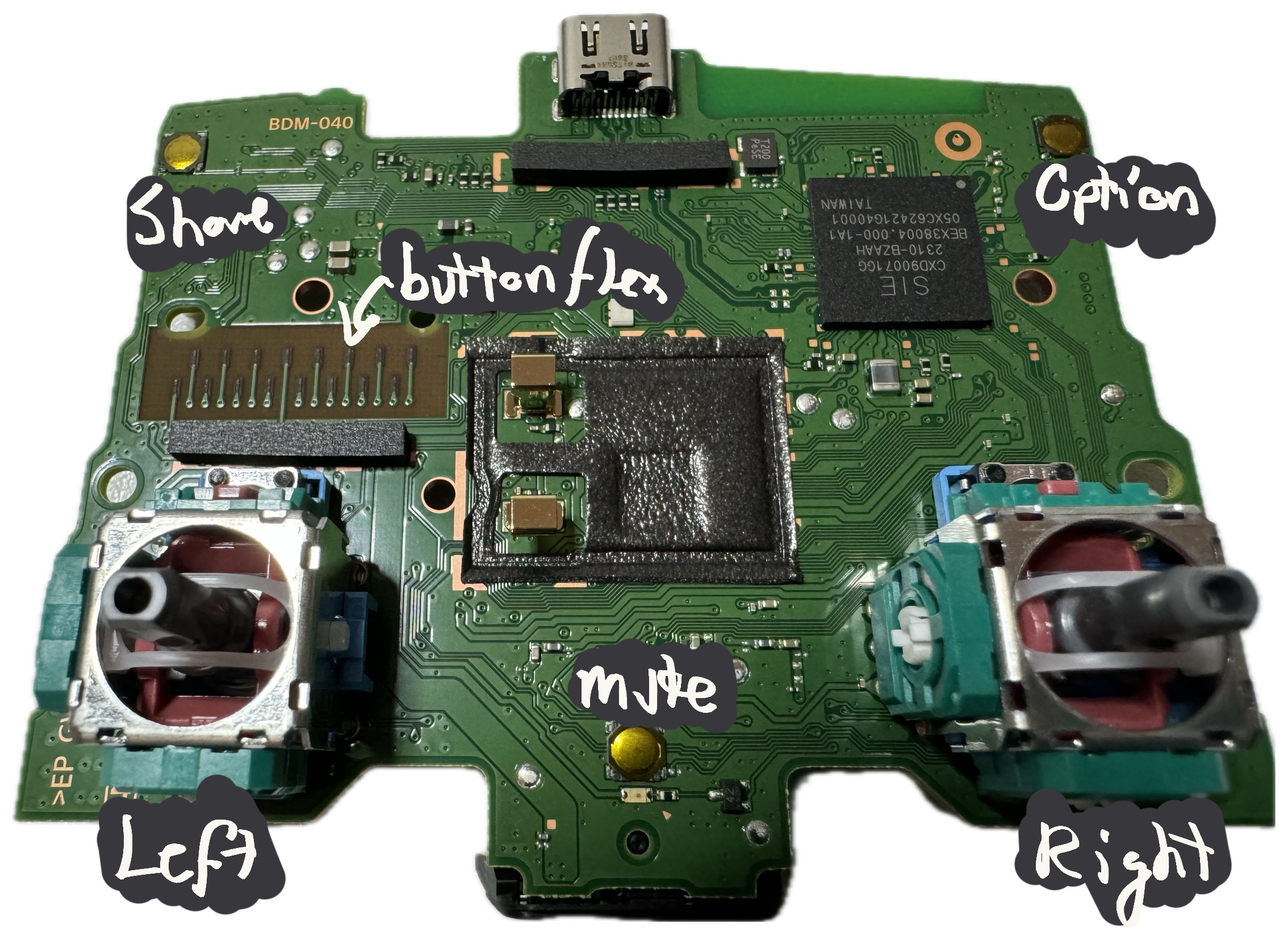
I wanted to ensure I received a controller with the latest board revision, BDM-040 (or at least BDM-030). The trigger button architecture was simplified significantly in this revision, allowing the majority of the signals to be connected directly to the spot that the button flex usually attaches.
-
I wanted to minimize the likelihood of having to debug a used controller, which might be damaged.
This thread on the AcidMods forum provides a wealth of information about the DualSense controller. I highly recommend reading through it in its entirety, but I will try to extract all of the necessary pieces of information and include them in this document. Credit for most knowledge included here goes to this thread’s contributors, other than a few small bits I learned through measurement.
The BDM-030 and BDM-040 revisions include the following signals on the button flex:
- Left, Right, Up, Down
- Square, X, Triangle, Circle
- L1, L2, R1, R2
- PS Button
Previous revisions inferred the value of L2 and R2 using the adaptive triggers’ feedback potentiometers. It’s certainly possible to build a controller using this signal path, but I decided to take the easier route if I could.
The remaining buttons not on this flex (which I refer to as “non-flex buttons” below) are:
- Share
- Option
- Mute
- Trackpad
- L3, R3
- The reset button on the back of the MLB
I decided on the following approach:
-
Rather than solder jumper wires directly to the button flex connector area, press a button remapper flex against it and solder to the pads of that flex. This minimized the number of destructive changes to the MLB. I decided to mount that flex to a small PCB and solder the pads out to a 14-pin connector, which I would then connect via ribbon cable to the controller board.
-
For the remaining buttons (except for the reset button), use jumper wires to connect them to a 10-pin connector that I would glue onto the spot where the speaker previously sat. I would then use a ribbon cable to connect that connector to the controller board as well.
-
Keep the adaptive feedback potentiometer boards and trackpad board attached to ensure the DualSense’s microcontroller did not need to deal with unexpected inputs, as I had no way of verifying its behavior without these things attached.
Wire Coloring
Because I had already committed to using the Brook wires to connect the buttons to the controller board, I decided to use the same colors all the way through the design. So, for example, if the PS button is orange, all of the wires in the system involved with the PS button path would be orange. This was honestly probably more effort than it was worth, as it is hard to trace these wires through anyways.
In a couple of cases, I used “adjacent” wire colors for the Controller rework, but later decided that wasn’t worth doing elsewhere.
I used purple for 1V8 and black for ground.
MLB Rework & Jumper Wires
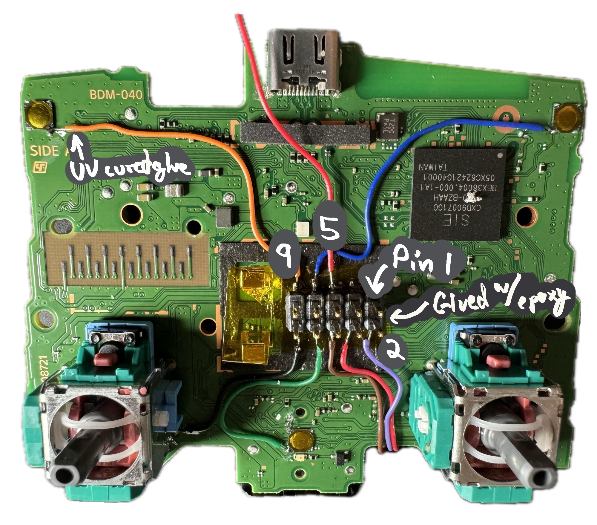
Thanks to the AcidMods thread and with the help of a multimeter to confirm, it was fairly easy to find the right spots to access the signals for the non-flex buttons, marked in yellow in the image below.
First, I soldered to each of the L3 and R3 buttons, as well as to the opposite post of the L3 button to get access to the 1V8 rail, which will be used on the controller board. These joints were most easily accessed on the bottom side of the board, so I carefully bent the wires around to the top side and used UV curing glue to hold them in place.
The Share, Option, and Mute buttons are surface mount and their pads are quite small, so it took a bit of finesse to make a secure connection.
I used UV-cured glue to help keep the wires in place and minimize the potential for breakage at the solder joint.
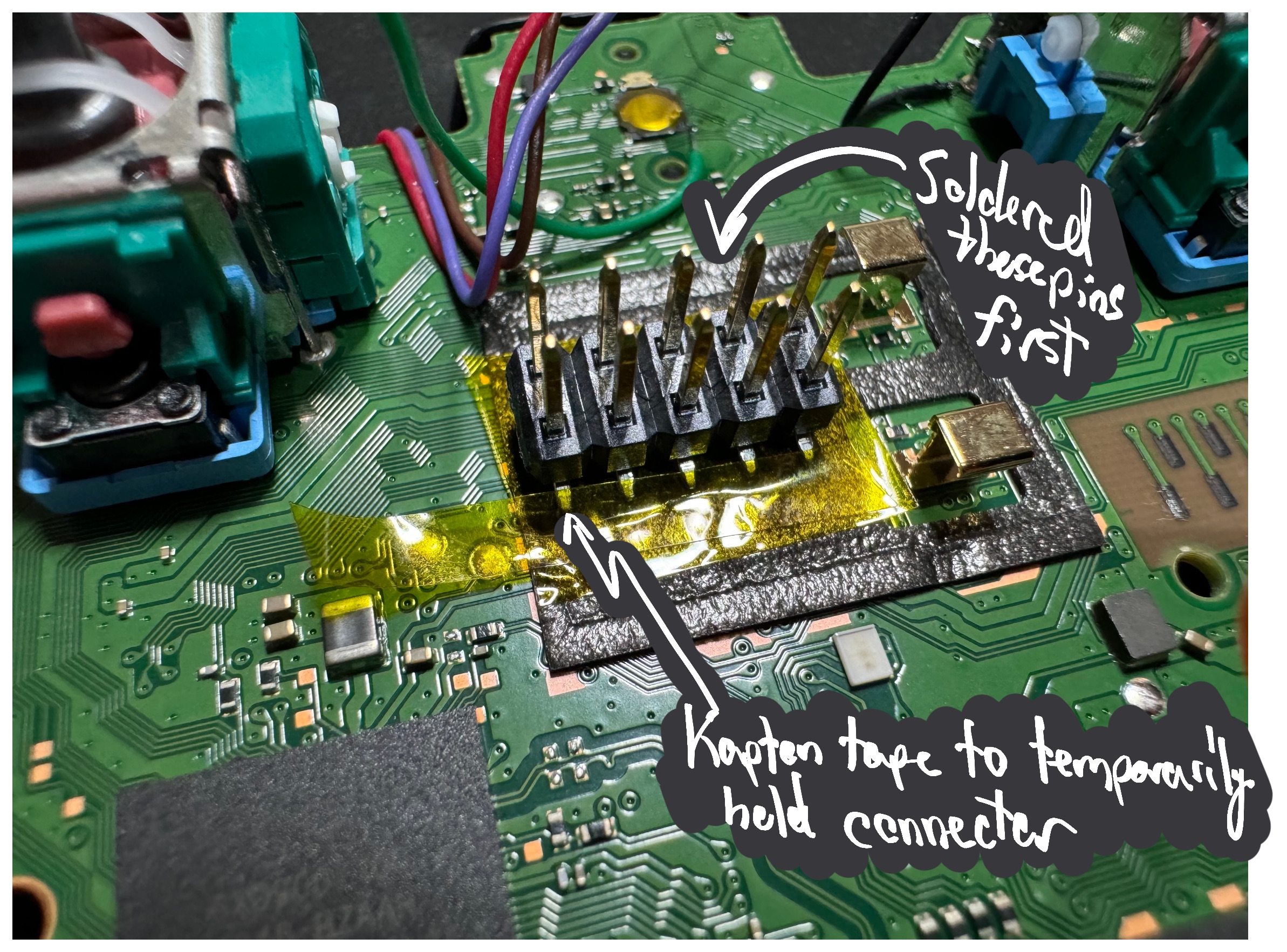
With all of these wires attached, I placed some Kapton tape on top of the foam area where the speaker used to sit, placed the vertical 10-pin SMT header on top of that and soldered the jumper wires to the bottom sides of the leads. The easiest way to do this was to place a small amount of Kapton tape on one side to hold it down and solder wires to the other side, then move the tape to the other side and repeat.
Once these were done, I soldered a long wire for the trackpad flex, which I would deal with later.
Lastly, I used some epoxy to glue the connector onto the Kapton tape. UV-cured glue might have worked too.
| Pin | Button |
|---|---|
| 1 | N/C |
| 2 | 1V8 |
| 3 | N/C |
| 4 | R3 |
| 5 | Trackpad |
| 6 | L3 |
| 7 | Option |
| 8 | Mute |
| 9 | Share |
| 10 | Ground |
Button Remapper Flex
Normally, the button remapper flex sits between the MLB and the DualSense’s actual button flex, but for this project, I used it a bit differently. I affixed the remapper onto a small protoboard with some double-sided tape and wired each of its pads out to the 14-pin connector.
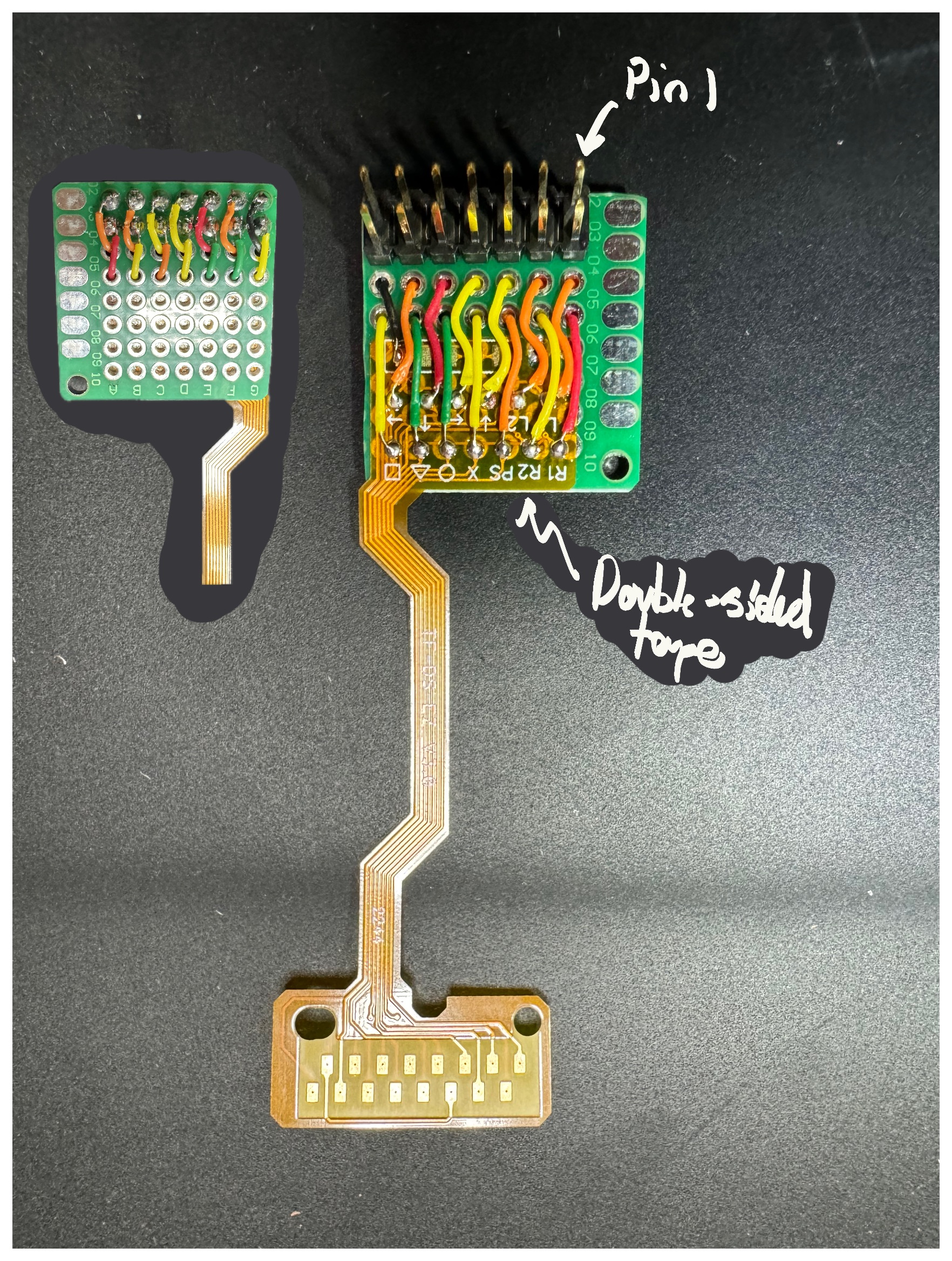
| Pin | Button |
|---|---|
| 1 | L2 |
| 2 | R1 |
| 3 | L2 |
| 4 | R2 |
| 5 | Down |
| 6 | PS |
| 7 | Left |
| 8 | X |
| 9 | Up |
| 10 | Circle |
| 11 | Right |
| 12 | Triangle |
| 13 | Ground |
| 14 | Square |
I actually purchased two remappers. The first one I purchased from Amazon seemed to have an entirely incorrect pinout. This one from Console Customs worked perfectly.
Trackpad Rework
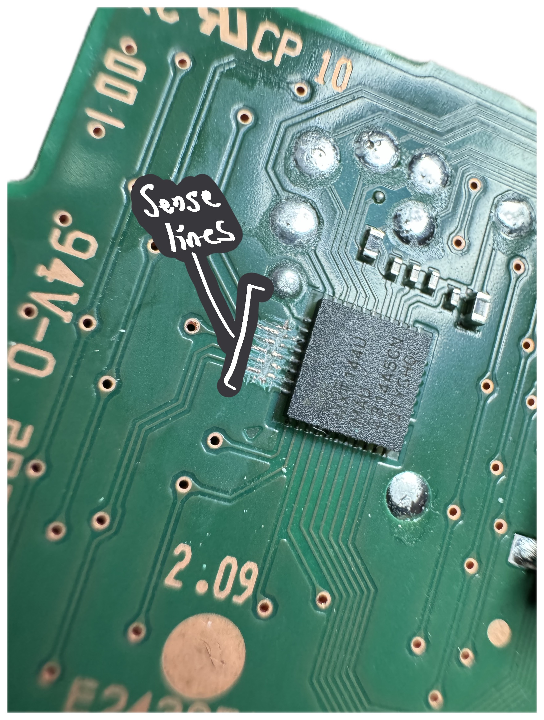
The system microcontroller on the MLB talks to an ATMXT144U touch controller on the trackpad board. Not wanting to perturb the behavior of the system microcontroller’s firmware, I wanted to leave this touch controller connected and I also wanted to ensure that the touch controller did not pick up any errant touch activity during use.
I considered two options: (1) ground the trackpad sensor entirely or (2) cut the sense traces. Grounding the sensor would be a non-destructive solution (just affix some grounded copper tape to the sensor), but, not knowing how the touch controller’s algorithms worked, could result in a situation where the controller might always detect some sort of large contact. I interacted with the sensor a bit and monitored both the drive waveforms and the I²C activity with an oscilloscope. The touch controller seemed to change its scanning operation depending on whether fingers were present and certainly increased I²C communication.
Grounding the sensor might result in the controller baselining on that signal after it is released from reset, but without any available documentation on the device, I opted to go the safer route of cutting the sense traces. Fortunately, this trackpad only uses the 6 sense traces at the top of the chip (pins 32 through 37), so it was relatively easy to cut them. I gently repeatedly scraped in a straight line on the traces using a thin razor until the traces began to appear. I then kept going until I could see the PCB substrate underneath. I used a multimeter to ensure that the sensor side of each broken trace was no longer connected to the corresponding controller pin.
Wiring Harness Rework
I thought I might save some time by purchasing Brook hitbox converter wiring harnesses. Typically you purchase one of these and connect them to a Brook controller wiring harness to replace the arcade stick. In my case, I purchased 5 in order to wire all buttons to the controller board via 0.1" connectors. Unfortunately, I did not realize that while their pitch was indeed 0.1", these harnesses use a flat connector pin, which is incompatible with a standard 0.1" rectangular header connector.
To resolve this, I used some spare right-angle SMT 0.1" header, as shown below:
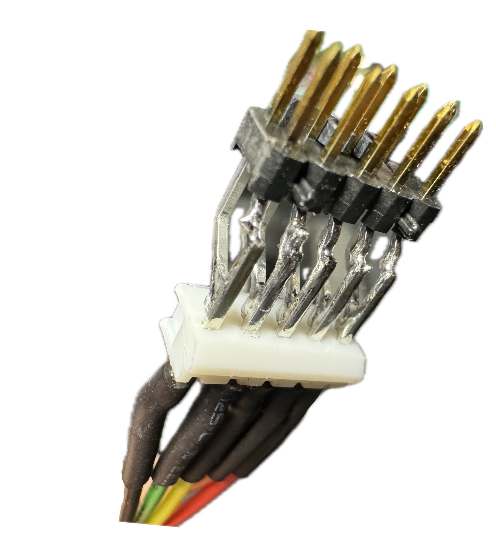
Assembly was a bit tedious:
-
Tin both connectors.
-
Tack the wiring harness pins onto one of the 0.1" header pins
-
Solder each of the long header pins
-
Also bridge to the short header pin
This spare header had 2 rows, so I connected the each pin to both rows. This provided the ancillary benefit of easily-accessible pins for connecting an oscilloscope or logic analyzer.
In the future, it is almost certainly worth creating custom wiring harnesses. Doing so will not only lead to cleaner routing within the controller but will also make it possible to use a more sensible interface.
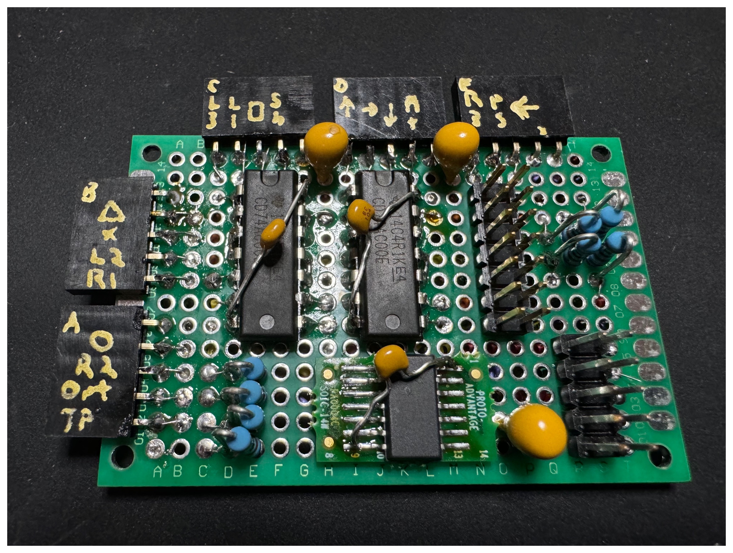
Controller Board
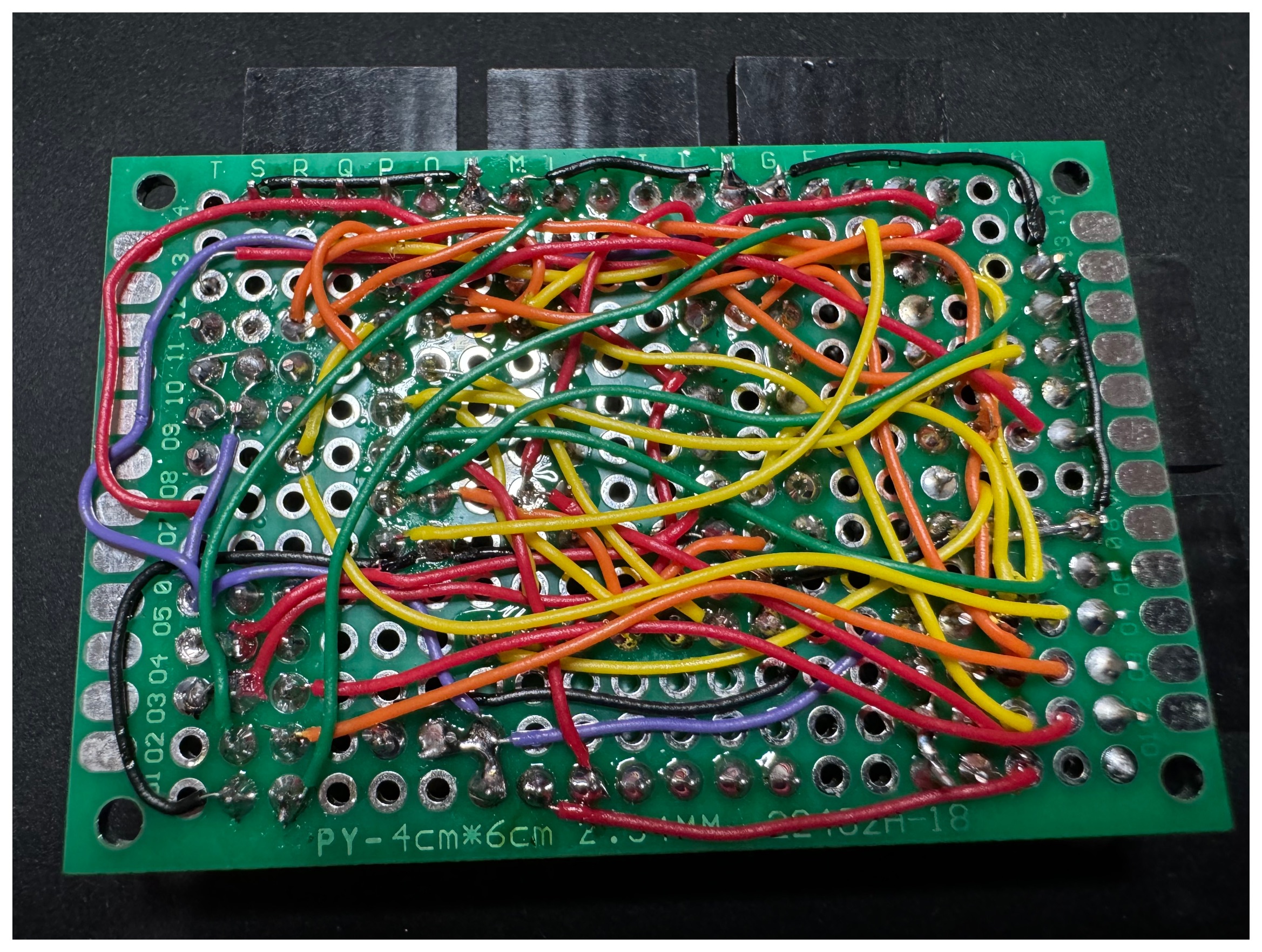
To map the signals from the buttons to those of the DualSense MLB, I built a small controller board using some protoboard. Despite its simplicity, the large number of nets made the assembly process tedious; a custom PCB will be a far better choice in the future.
Button Connection Scheme
Because I was using a number of discrete wiring harnesses, it was necessary to establish groups of 4 nearby buttons. The resulting wiring scheme looks like this:
| Group | Pin | Button |
|---|---|---|
| A | 0 | Trackpad |
| A | 1 | Option |
| A | 2 | R2 |
| A | 3 | Circle |
| A | 4 | Ground |
| B | 0 | R1 |
| B | 1 | L2 |
| B | 2 | X |
| B | 3 | Triangle |
| B | 4 | Ground |
| C | 0 | L3 |
| C | 1 | L1 |
| C | 2 | Square |
| C | 3 | Share |
| C | 4 | Ground |
| D | 0 | Up |
| D | 1 | Right |
| D | 2 | Down |
| D | 3 | Mute |
| D | 4 | Ground |
| E | 0 | R3 |
| E | 1 | PS |
| E | 2 | Left |
| E | 3 | N/C |
| E | 4 | Ground |
Button Polarity
All buttons on the DualSense controller are active-low except for L3 and R3, which are active-high. Thus, for the majority of the buttons on my controller, I could simply wire one button pin to ground and the other directly over to the DualSense MLB.
For L3 and R3, instead of treating these specially on my controller, I opted to make them active-low like the others and then provide an inverted copy of their value to the DualSense MLB. That way, all buttons could be connected using the same ground loop.
SOCD Cleaning
Simultaneous Opposite Cardinal Directions (SOCD) is a unique aspect of leverless controllers. For example, one can press both the left and right buttons on a leverless controller simultaneously, but this is not physically possible with an arcade stick or a gamepad. Games often “clean” such inputs (make a decision when such situations occur), but the controller hardware can also do this. There are a few different cleaning algorithms, but from my research, it seems like the most commonly accepted one is:
- Left + Right = Neutral
- Up + Down = Up
Handling this on the controller board is fairly straightforward with some logic gates. The truth tables for these are as follows:
Left_L | Right_L | Left_cln_L | Right_cln_L |
|---|---|---|---|
| 0 | 0 | 1 | 1 |
| 0 | 1 | 0 | 1 |
| 1 | 0 | 1 | 0 |
| 1 | 1 | 1 | 1 |
Down_L | Up_L | Down_cln_L | Up_cln_L |
|---|---|---|---|
| 0 | 0 | 1 | 0 |
| 0 | 1 | 0 | 1 |
| 1 | 0 | 1 | 0 |
| 1 | 1 | 1 | 1 |
Therefore, for Left, Right, and Down, the logic to clean them is X_cln_L = (NOT X_L) NAND (Y_L).
That is, if you want to cancel Left_L when Right_L is pressed, you want the inverted value of Left_L (Left) NANDed with Right_L. When Left and Right are both pressed, Left_L==0 → Left==1 and Right_L==0, and so 1 NAND 0 == 1, meaning “not pressed”. The analogous logic applies for Right and Down.
The “cleaned” version of the Up direction is simply the same as itself because when you press both Up and Down, you still get Up.
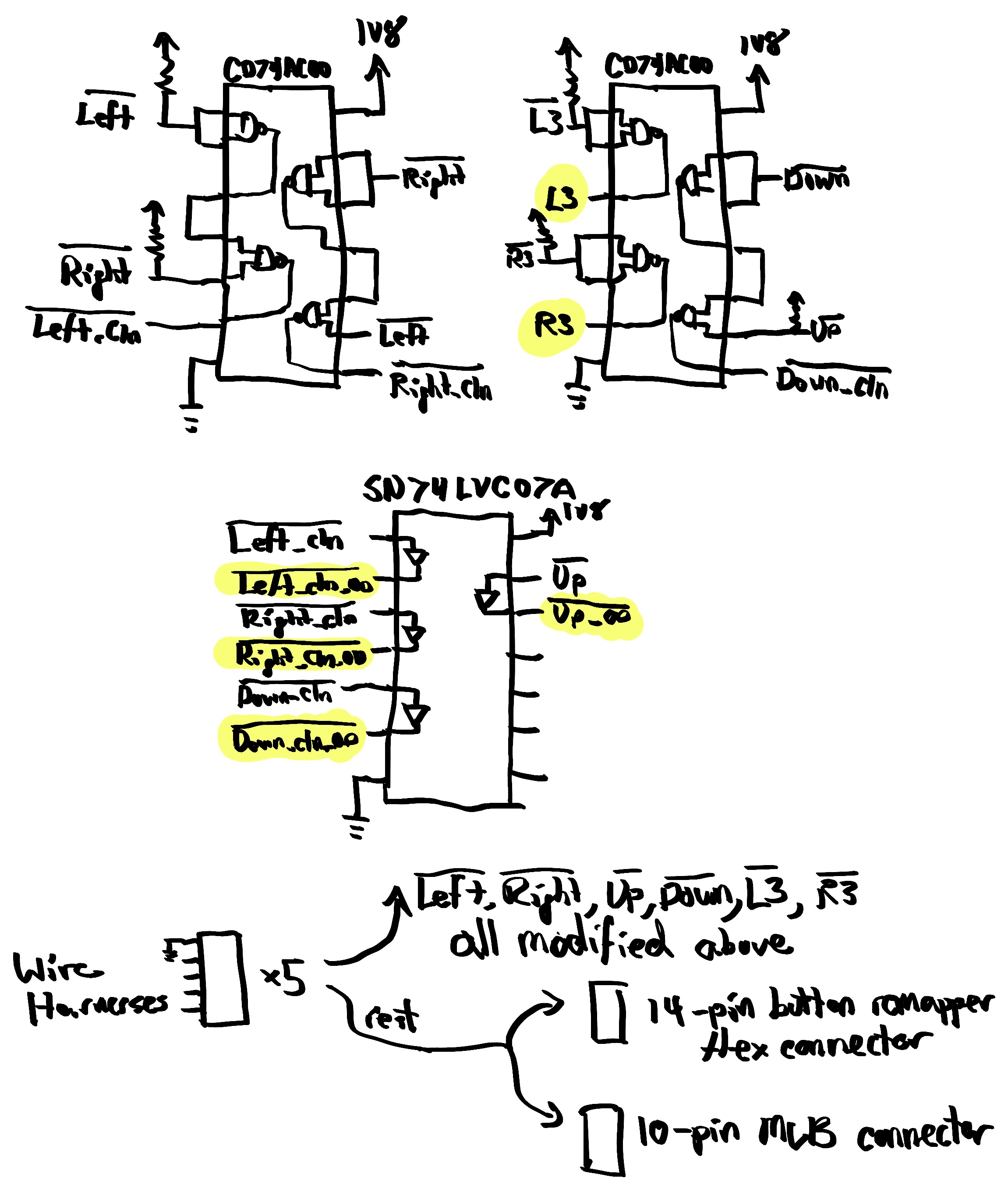
The easiest way to implement this is to place pull-up resistors on the directional buttons and then build the aforementioned logic out of quad NAND gates (such as CD74AC00E, which supports 1.8V logic). Feeding the same signal into both ports of a 2-input NAND gate makes it a NOT gate, so we can implement the above logic (as well as the L3 and R3 inversion) as shown in the diagram below.
Additionally, to maintain parity with the way that the active-low buttons interface to the MLB on the DualSense controller, I added an open-drain output buffer (SN74LVC07A) so that the signals would never actively be driven high by the controller board. I also included the signal for Up as well to isolate the external pull-up resistor I applied to that signal on the controller board.
L2 and R2 Pull-Up
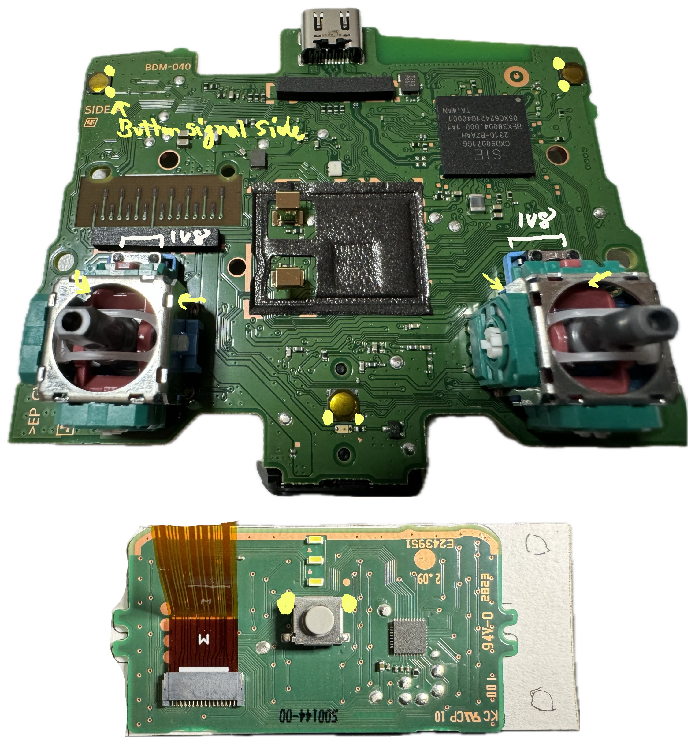
All of the active-low buttons are pulled up on the MLB (either by discrete resistors or by the microcontroller — I haven’t looked into which) except for L2 and R2. These appear to be pulled up using a pair of embedded flex resistors on the button flex itself. They’re located here:
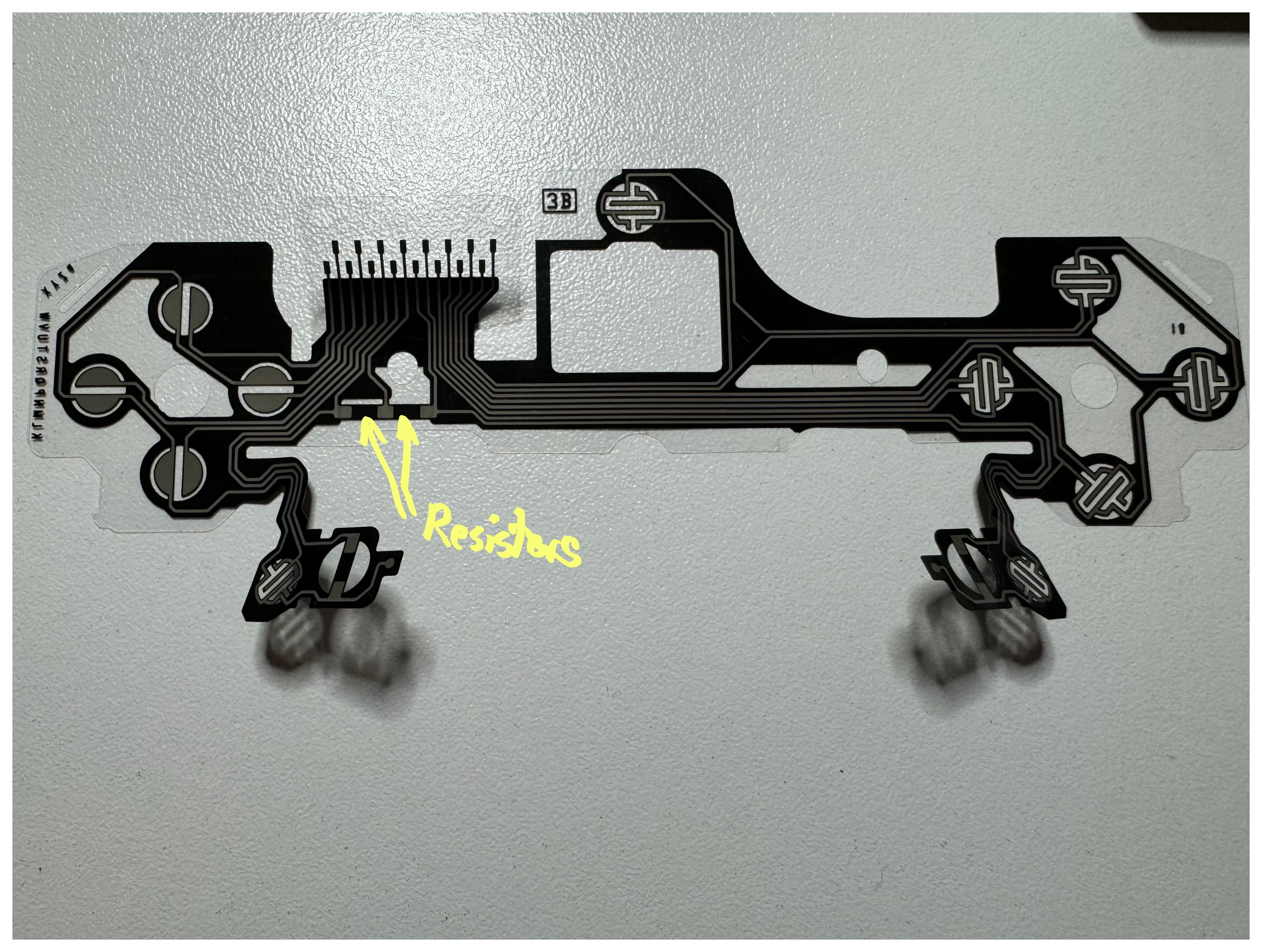
Therefore, to mimic the behavior of the button flex, it was necessary to add 10K pull-up resistors on the controller board for these signals.
Controller Board Layout
The final schematic for the controller board is fairly simple:
However, the protoboard layout was anything but.
Recognizing the looming fit challenge, I opted to make the board as small as physically possible. Compact usages of protoboard are challenging, as they involve a great deal of point-to-point wiring. Layout and assembly was tedious and required great care, as mistakes would be difficult to debug. It would be far better to build a custom PCB for this board.
Assembly
With all of the electrical components built, it was time to perform the assembly.
Enclosure Assembly
To assemble the enclosure, I simply followed the recommended directions from the seller (minus the instructions to install the Brook controller board).
I chose to use Samducksa Crown SDB-202 buttons. I initially did not screw them in tightly in order to allow for some adjustment during the fit-check process.
DualSense MLB Assembly
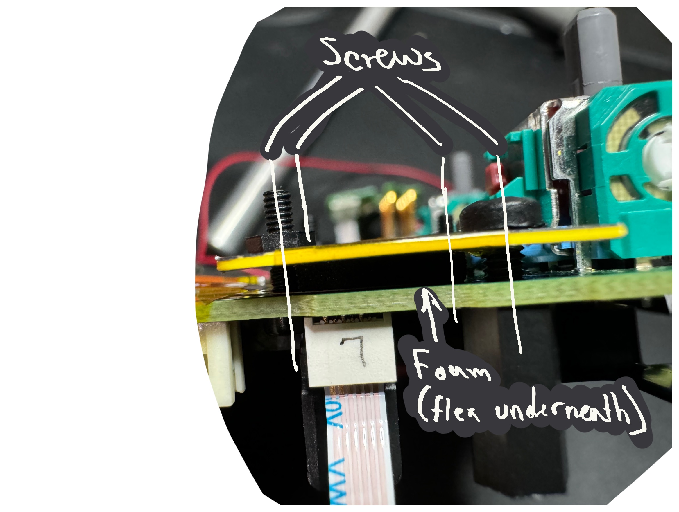
Normally, the button remapper flex connects to the DualSense MLB underneath the typical button flex (and the whole assembly presses up against the chassis of the DualSense controller). For this project, I had to improvise a bit. I traced out the shape of a “bracket” that would hold the remapper flex onto the MLB pads via the surrounding screws. I then cut that shape out of an old credit card and drilled holes where the corresponding holes in the MLB were. I then sandwiched the remapper flex between this card and the MLB and screwed them together with standoffs. When I tested this design out, I discovered that most of the pins were not making good contact. So, I modified the design a bit by cutting out a small piece of foam exactly the size of the remapper flex’s outline and affixed that to the bracket. This way, when I screwed the bracket to the MLB, all of the pressure would be placed on the flex contacts.
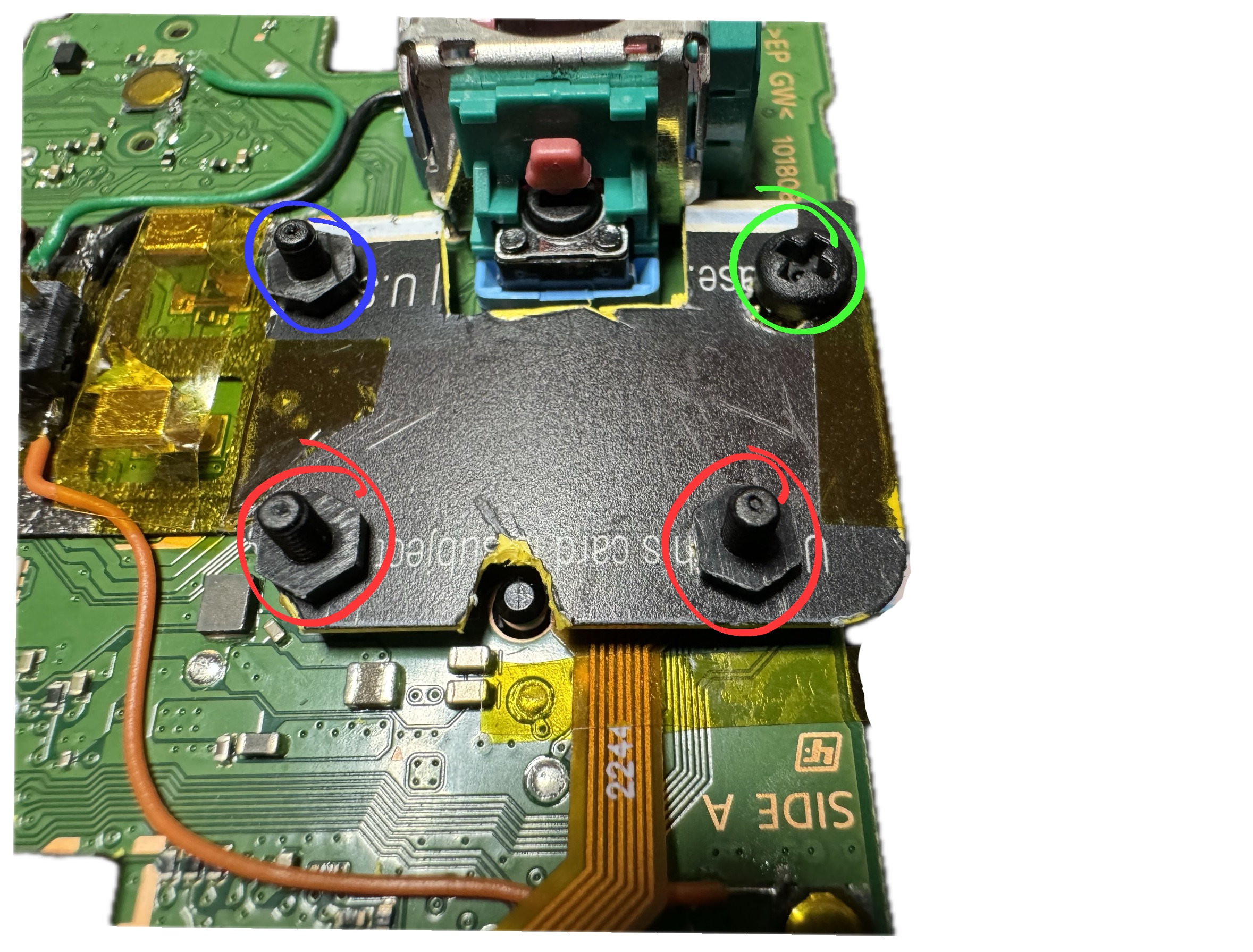
I placed the battery underneath the MLB using the controller’s original battery bracket. To do this, I first affixed the two M2 screws & nuts whose heads would be hidden underneath the bracket (labeled in red in the diagram below). Then, I placed the battery bracket on the back of the MLB and used another M2 screw (labeled in blue) to screw both the battery bracket and the flex bracket all together. The final M2.5 screw in green then screws into a standoff, which will be attached to the enclosure chassis next.
With the flex, flex bracket, and battery brackets attached, I then attached the two adaptive trigger flexes back onto the MLB, as well as the trackpad flex. I did not come up with a great way to affix these flexes; ultimately, I ended up placing some Kapton tape over the surface of the trackpad sensor and then some adhesive foam onto that, flipped it over so that it sat atop the MLB, and then used some double-sided tape to secure it. I then flipped the adaptive trigger flexes so that they were atop the MLB as well and used Kapton tape to secure them to the trackpad board. Once everything was attached, I took the wire that I had reserved for the trackpad button and brought it over to the trackpad board, soldering it to the pin of the trackpad button (I suppose this technically violates Goal 1, but the DualSense assembly is essentially a single module, so it’s on the edge). I used some more UV curing glue to secure the wire.
Lastly, I screwed in M2.5 standoffs for the two outer holes of the MLB. Having just two holes was somewhat precarious, but I chose standoffs sized so that after adding a layer of foam to the battery, they would be just about even with it. That way, the battery would prevent the board from rocking. I also attached a singular standoff for the only hole in the remapper’s PCB and glued a second standoff to it later on for stability.
With that, the DualSense board was completely assembled and ready for installation.
Wiring and Fit-Check
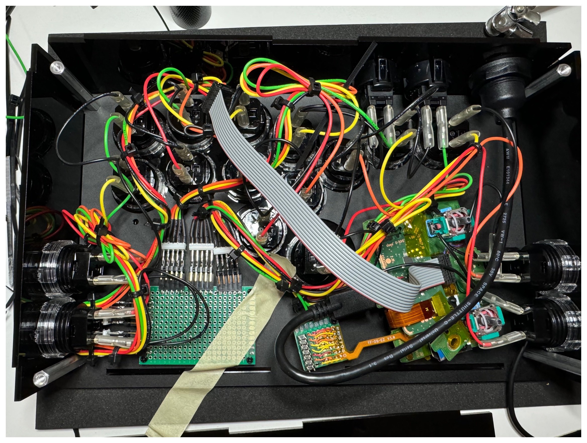
I opted for one of Eternal Rival’s smaller enclosure sizes realizing it would be a tight fit. It was important to work iteratively in order to find the best assembly option. First, I wired up all of the buttons according to the button connection scheme in order to get a sense of how cramped things would be. Next, I assembled a fake controller board (just the header receptacles soldered) so that I could manipulate the wiring harnesses without fear of damaging the actual controller board.
I worked through each wiring harness to clean it up by tying up bundles and then connecting each group to the fake controller board.
Next, I carefully placed in the DualSense MLB and button flex board to find the optimal placement. I had to bend one of the button terminal’s pins in order to fit this board. I also had to remove the strain relief on the audio jack.
After completing the fit-check, I tightened all of the buttons and I drilled a 1/4" hole in the front panel at a location I would be able to reach with the audio jack passthrough.
Final Assembly
Once I was satisfied with the placement, I made note of the location, removed the DualSense MLB, and replaced the fake controller board with the real one, to which I installed standoffs on each corner. Rather than trying to drill new holes into the enclosure for the standoffs, I carefully glued them instead. After the controller board was affixed, I repeated the process for the DualSense MLB and the remapper PCB (only gluing the screwed standoff) after having confirmed that the ribbon cables would fit properly.
I remain somewhat concerned about the long-term stability of using glued standoffs. A better approach would probably be to build a bracket that converts from the standoff locations to the Brook controller board mounting holes. Even then, such a bracket would be quite large, so some sort of adhesive or additional screw on the opposite side of the 30mm button would be necessary.
With all boards installed and all cables now connected, I used a pair of tweezers to insert the battery connector in to the MLB’s receptacle.
Testing
Throughout the electrical work, I periodically tested the design by installing the battery and using tools like this gamepad tester to observe button functionality and an oscilloscope to verify signal integrity.
-
I first spot-tested a few buttons before performing any rework on the MLB.
-
Then, after reworking the non-button-flex buttons onto the 10-pin connector, I tested those by grounding each of the active-high pins and then raising each of the active-low pins to 1V8.
-
The next test occurred after installing the soldered button remapper flex. This test was important, as I first discovered that my bracket needed to apply more localized pressure onto the flex outline. Once that was corrected, I was able to check each of the pins by grounding them (except for L2 and R2, which required pull-ups on the controller board).
-
Then, before installation into the enclosure, I connected the MLB to the controller board and tested end-to-end functionality of every button input into the board by grounding each button cable pin, one by one. I discovered that I had forgotten to connect the pin carrying 1V8 into the controller’s 1V8 net, which was easily discoverable and fixed.
-
Lastly, after installing all of the boards, I did one final test before closing the unit up. I also monitored the touch controller’s traces to confirm that it was not generating any traffic to the microcontroller.
Future Work
There are a few things that could improve both the robustness and the build complexity of this project. In particular, the interior space is fairly cramped, especially around the boards, and I would like to reduce cramping to make it easier to install and repair the boards.
-
Switch from protoboard to a custom controller PCB. This will reduce the PCB size and will save an entire evening of soldering point-to-point connections. With a custom PCB, I would use SOIC packages directly and would use SMT resistors. Likewise, it would be prudent to build a custom PCB for the button remapper flex as well.
-
Choose smaller ribbon cables and connectors. The 0.1" pitch connectors and correspondingly large ribbon cables were unwieldy. It should be easier to move to much smaller, more flexible cables without DCR or SI concerns.
-
Build custom wire harnesses with more sensible connection strategy to the controller PCB. This was arguably the biggest mistake, as it generated the majority of the cramping. In a future design, I’d simply just crimp my own connectors and run a single ground loop through all of the buttons. As for connection to the controller board, I might opt for small screw terminals instead of .1" rectangular header, as they are more secure.
-
Build a mounting bracket for the controller and DualSense MLB. This approach would simplify the installation process and eliminate the need to glue the standoffs.
Beyond that, it would be nice to eliminate the need for the adaptive trigger boards and the trackpad board. The adaptive trigger boards solely consist of a potentiometer at this point, so perhaps one could rework the correct resistor divider network directly onto the MLB. The trackpad board is trickier to eliminate; it would probably require a custom PCB with the same flex connector and touch controller installed; a custom PCB could be much smaller than the trackpad board and be designed to mount more securely to the DualSense MLB.
As for additional features, it should be possible to add LEDs to the enclosure, either by desoldering and replacing the DualSense MLB’s LEDs or perhaps by installing some simple lightpipes using the original LEDs on the MLB.